
In production, a machine vision station typically fails for a few repeatable reasons: the lens doesn’t match the working distance and field of view, lighting isn’t controlled, triggering varies cycle-to-cycle, or calibration drifts until pass/fail thresholds become unreliable. This tutorial gives a practical, repeatable setup flow for a basler camera used in inspection and code reading—covering lens selection, lighting strategy, triggering/I-O, and calibration and verification.
The goal is not “a picture on the screen.” The goal is a stable inspection channel that survives shift changes, part variation, ambient light changes, and vibration—so the station keeps rejecting bad parts and passing good ones without constant re-tuning.
Assumptions: you’re an automation engineer integrating vision into an existing line (conveyor, index table, robot cell, test station) using a PLC/robot controller or PC-based vision app. Specific Basler models, interfaces (GigE, USB3, CoaXPress), and software vary, but the engineering principles stay the same.
1) Define the inspection requirement before touching hardware
Lock down what “pass” and “fail” mean in engineering terms before choosing optics or lighting. Clear requirements prevent over-buying resolution and chasing impossible lighting.
1.1 Clarify the task type
- Presence/absence: component installed, clip missing, screw present.
- Orientation/position: label rotation, connector shift, assembly alignment.
- Defect inspection: scratches, contamination, solder bridging, voids, insufficient fill.
- Code reading: 1D/2D (Data Matrix/QR), DPM, small codes on reflective surfaces.
- Measurement/metrology: gap, diameter, edge-to-edge distance, pitch checks.
Task type drives optics and lighting. Reflective defect inspection often needs glare control (dome/coaxial/low-angle). Code reading on moving parts usually needs high contrast and short exposures to freeze motion.
1.2 Specify key mechanical facts
- Working distance (WD): lens-to-part distance (include any window/guard).
- Field of view (FOV): area to cover in mm (include placement margin).
- Part motion: conveyor speed, index settle time, vibration.
- Depth variation: expected Z tolerance/warpage/fixture variation.
- Cycle time: max acquisition + processing time.
- Environment: dust/oil/flux fumes, washdown, ESD constraints.
Capture this in a short “vision requirement” note. You’ll use it when selecting lenses/lights, setting exposure, and deciding whether you need an enclosure to block ambient light.
2) Choose the camera configuration that matches your inspection physics
Even though this is a setup tutorial, a few configuration choices strongly affect everything downstream.
2.1 Area scan vs line scan (quick guidance)
- Area scan: common for stationary or indexed parts and general inspection.
- Line scan: best for continuous motion and long/wide surfaces; requires encoder synchronization.
If you can trigger as a part passes a sensor (or when an index settles), area scan is usually simpler. If the product never stops and you need uniform high resolution across long lengths, consider line scan.
2.2 Resolution and pixel size: target sampling, not “max pixels”
Start from the smallest feature/defect you must resolve and design for ~3–5 pixels across the smallest critical dimension. More pixels can help, but increase bandwidth, processing load, and sensitivity to focus and lighting.
Example: to reliably detect a 0.2 mm edge nick, design for ~0.04–0.07 mm/pixel at the part plane, then confirm the full FOV fits the sensor resolution.
2.3 Shutter mode and frame rate considerations
- Global shutter is preferred for moving parts to avoid skew artifacts.
- Short exposure freezes motion but requires more light (often strobed).
- ROI improves frame rate and reduces bandwidth when you only need part of the image.
In many factories, lighting capability and control limit performance more often than nominal camera frame rate.
3) Lens selection: calculate magnification, then manage distortion and depth of field
The lens defines your imaging geometry. A good camera with a mismatched lens produces inconsistent images that are hard to “fix in software.”
3.1 Step-by-step: pick focal length from FOV and working distance
- Determine required FOV (mm) with margin for placement variation.
- Confirm sensor size (from the camera datasheet).
- Compute magnification: M ≈ sensor dimension / FOV dimension (use the limiting axis).
- Estimate focal length: f ≈ WD × M / (1 + M) as a starting point; confirm with vendor calculators/datasheets.
- Verify mechanical fit: mount type (C/CS/F), barrel clearance, lighting space, and any window thickness.
If you will replicate the station across lines, standardize WD and bracketry early. Small geometry differences drive later re-tuning.
3.2 Use telecentric lenses when measurement accuracy matters
Telecentric optics reduce perspective error (magnification changes with depth) and help when parts have Z variation but you need consistent edge location. Trade-offs: cost, size, and sometimes lighting constraints.
For simple presence checks, standard lenses are often fine. For metrology-like tasks (gap, pitch, tight tolerance edges), telecentric lenses can reduce false rejects and re-calibration effort.
3.3 Depth of field vs aperture: avoid trading stability for blur/noise
Stopping down increases depth of field but reduces light. If that forces longer exposures, you may introduce motion blur and noise. Prefer building enough controlled illumination (often strobed) so you can run a reasonable f-number while keeping exposure short.
- If focus is unstable: improve fixturing/hard stops or consider telecentric optics.
- If exposure becomes too long: increase lighting or strobe with the trigger.
- If diffraction softens edges (very high f-number): open slightly and improve lighting uniformity.
3.4 Distortion and calibration implications
Barrel/pincushion distortion can impact measurement and even code reading near the edges. If geometry matters across the full FOV, select low-distortion optics and include distortion correction in your calibration workflow.
4) Lighting strategy: design contrast first, then make it repeatable
Most “camera problems” are lighting problems. Good lighting means the same part condition produces similar pixel values regardless of ambient changes.
4.1 Step-by-step: choose illumination type by surface and feature
- Identify the feature: edge, embossed text, scratch, hole, solder fillet, printed label, reflective metal.
- Choose contrast direction: feature bright-on-dark or dark-on-bright.
- Select geometry:
- Ring light: general-purpose, easy for short WD.
- Bar/low-angle: emphasizes texture, scratches, engravings.
- Backlight: silhouettes for edge/slot/hole measurement.
- Dome: reduces glare on curved/reflective parts.
- Coaxial/on-axis: strong for flat reflective surfaces and many printed marks.
- Confirm uniformity across the FOV plus margin.
- Plan control: continuous vs strobed, intensity control, and whether ambient must be blocked.
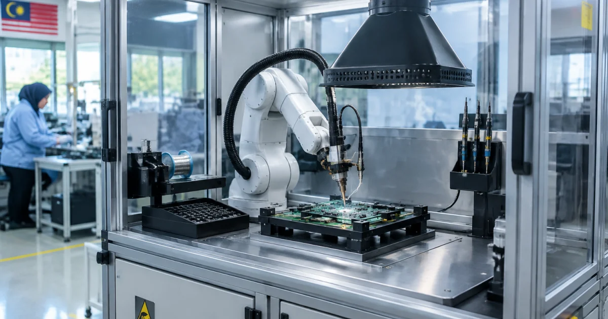
For solder-related inspection (for example after an auto soldering machine operation), glare control is often the deciding factor. Dome or coaxial lighting can reduce specular hotspots that break threshold-based checks.
4.2 Continuous vs strobed lighting (why strobes often win on moving lines)
- Continuous lighting is simpler but often forces longer exposures, increasing blur sensitivity.
- Strobed lighting enables very short effective exposure, freezes motion, and can overpower ambient light.
On conveyors, hardware triggering + strobed lighting is one of the fastest paths to repeatable images.
4.3 Polarizers, diffusers, and enclosures
For reflective surfaces (metal housings, solder joints, glossy packaging), consider:
- Cross-polarization: polarizer on the light + analyzer on the lens to reduce glare.
- Diffusers: smooth hotspots (but may reduce texture contrast).
- Vision enclosure: often the most effective fix for ambient variability (skylights, door openings).
5) Mounting and mechanics: lock geometry before software tuning
Stable mechanics turn tuning into a one-time task. Unstable mechanics turn tuning into ongoing maintenance.
5.1 Mounting checklist
- Rigid bracket with minimal cantilever; avoid resonant arms.
- Maintainable access to focus/aperture without dismantling guards.
- Fixed reference surfaces (dowel pins/machined faces) to return to a known pose.
- Cable strain relief to prevent connector movement and intermittent faults.
- Protective window if needed (optical-grade, cleanable); account for reflections.
5.2 Working distance and angle: keep it simple
A perpendicular view is usually easiest to calibrate and best for measurement. If you must tilt (sidewall visibility or reflection avoidance), lock the angle mechanically, document it, and plan for perspective-aware calibration.
5.3 Robot and end-effector interactions
In robot cells, repeatability depends on how the part is presented (grip force, jaw wear, seating). Whenever possible, use a hard stop/locating feature at the presentation pose, and trigger only after a confirmed motion-complete signal plus a short settle time.
6) Triggering and I/O: make acquisition deterministic
If images are captured at slightly different part positions each cycle, algorithms must be overly tolerant (or they will be unstable). Deterministic triggering is a core reliability requirement.
6.1 Decide on trigger source: PLC, sensor, encoder, or robot
- Photoelectric sensor: common for conveyors; trigger at the edge, then apply a repeatable delay to center the part in the FOV.
- PLC output: good for indexed stations where the PLC controls settle point.
- Encoder: best for continuous motion where capture must be position-locked.
- Robot DO: trigger at a known pose after motion complete and settle.
6.2 Wiring concepts: opto-isolated I/O and grounding
Industrial noise affects triggers and strobes like any other control line:
- Use shielded cables when appropriate and route away from motor power.
- Prefer opto-isolated I/O for trigger and strobe control.
- Apply single-point grounding concepts to reduce ground loops.
- Document the I/O map (trigger, busy, OK/NG, fault) and timing expectations.
If you strobe the light, decide whether the camera supplies the strobe output or the PLC triggers both with known timing. A common robust pattern is: sensor/PLC triggers camera; camera outputs strobe; light strobes during exposure.
6.3 Trigger mode setup and verification steps
- Start in free-run to confirm optics, focus, and baseline image quality.
- Enable hardware trigger and confirm acquisition occurs only on trigger edges.
- Check missed triggers: pulse width, voltage levels, debounce for mechanical sensors.
- Check timing jitter: investigate OS scheduling, USB hubs, or network congestion if timestamps vary widely.
- Lock exposure and other parameters to manual once lighting is stable; avoid auto features unless you have a controlled, validated reason.
7) Image tuning: exposure, gain, ROI, and focus using a repeatable method
With mechanics, lighting, and triggering stabilized, tune the image so algorithms receive consistent input.
7.1 Step-by-step tuning workflow
- Set target exposure time based on motion (short enough to freeze it).
- Increase light intensity or enable strobe to reach target brightness at that exposure.
- Keep gain low; add gain only after you have maximized useful light.
- Adjust aperture for depth of field, then re-check exposure and brightness.
- Set ROI to the smallest region containing the inspection features (speed and stability).
- Lock white balance for color tasks; for many inspections, monochrome + controlled light is more robust.
7.2 What “good” looks like (practical acceptance checks)
- No clipping on critical features unless saturation is intentional.
- Stable histogram across 30–50 samples (similar brightness distribution).
- Edge sharpness at the target plane and expected Z extremes.
- Motion test at real line speed: confirm no blur and consistent part position.
7.3 Practical example: code reading on a moving conveyor
Common failure modes are blur and low contrast. A stable approach:
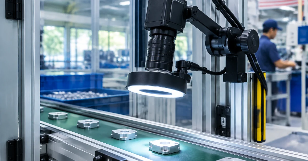
- Use a strobed ring or bar light positioned to avoid direct label glare.
- Set short exposure, then increase strobe intensity to maintain brightness.
- Reduce ROI to the code region to improve speed and reduce bandwidth.
- Trigger from a sensor and apply a repeatable delay so the code lands in a consistent image location.
Consistency comes from aligning mechanical presentation, trigger timing, and lighting—not from endlessly tweaking decode parameters.
8) Calibration and validation: turn images into reliable decisions
Calibration is how you keep performance predictable after maintenance, camera replacement, or small mechanical shifts.
8.1 Decide what you must calibrate
- Pixel-to-mm scale: required for dimensional thresholds.
- Lens distortion correction: important when geometry accuracy is needed across the FOV.
- Hand-eye/robot alignment: needed when vision guides robot motion or verifies placement.
- Illumination normalization: flat-field correction can help under non-uniform light.
8.2 Step-by-step: basic pixel-to-mm calibration
- Finalize mechanics: camera/lens mounted, focus and aperture locked.
- Place a calibration target at the same plane as the inspected feature (or the most critical plane).
- Capture multiple images using production lighting and exposure.
- Compute scale (mm/pixel) and distortion parameters if supported.
- Validate by measuring known distances at the center and corners; record residual error.
- Lock and version configuration (camera settings, calibration files, thresholds).
If you need accurate measurements across the full FOV with a standard lens, distortion correction becomes more important. If you can constrain measurements to the central region, distortion sensitivity is reduced.
8.3 Validation for pass/fail inspection (golden sample method)
Even without mm measurement, validate robustness with a structured sample set:
- Golden good parts: known-good samples across expected variation (lot, shade, finish).
- Known-bad parts: representative defects (missing component, wrong orientation, solder bridge, damaged label).
- Borderline parts: near-threshold cases to avoid over-tuning.
Run a short production-like trial (real motion, real operators, realistic ambient). Document false rejects, missed defects, and any warm-up drift.
8.4 Maintenance plan: keep the system stable over months
- Cleaning routine: lens window and lighting diffuser; set interval by environment.
- Mechanical checks: bracket fasteners, sensor alignment, cable strain relief.
- Re-calibration triggers: camera/lens replacement, collision, bracket adjustment, significant line changes.
- Spares: keep critical drivers/controllers when downtime is costly.
These basics often separate a lab demo from a reliable factory vision inspection machine.
Useful next reads and Basler product options
- Basler Area Scan Cameras for common inspection and code reading stations.
- Basler Line Scan Cameras for continuous motion and wide-surface inspection.
- Basler 3d Cameras when height/volume information is needed.
- Basler Camera accessories and options for building a complete station.
Conclusion: a production-ready setup is a controlled system, not just a camera
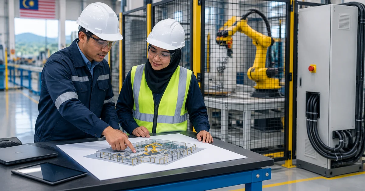
A reliable Basler-based machine vision station comes from controlling the full chain: optics that match FOV and tolerances, lighting that creates stable contrast, deterministic triggering that captures the part at the right moment, and calibration/validation that preserves repeatability after maintenance. If you follow the sequence—requirements, mechanics and lighting, triggering, image tuning, then calibration—you reduce time spent chasing vision issues and increase uptime and inspection consistency.
If your inspection is part of a broader automation cell (robot handling, conveyors, post-process checks after soldering), treat vision as a system design element. Done well, it becomes a dependable quality gate and a foundation for scalable factory automation.
Frequently Asked Questions
How do I choose the right lens for a Basler machine vision inspection setup?
Start with the required field of view (mm) and working distance, then calculate the needed magnification and an estimated focal length. Next, check depth of field versus aperture, and decide whether you need a telecentric lens (recommended for tighter measurement tasks or when part height varies). Finally, verify mechanical fit and consider low-distortion optics if you measure features across the full image.
Should I use continuous lighting or strobed lighting for conveyor inspection?
If parts move, strobed lighting is usually more robust because it enables very short effective exposure to freeze motion and reduce ambient-light influence. Continuous lighting can work for indexed stations or slow lines, but it often forces longer exposures that increase blur and variability. In many factories, the most stable approach is hardware triggering plus a strobed light timed to the camera exposure.
What is the simplest reliable way to trigger a camera for inspection on a production line?
A common reliable method is a photoelectric sensor to detect the part, then a PLC (or the camera) applies a consistent delay so the part is in the same position when the image is captured. For continuous motion where position accuracy is critical, use an encoder-based trigger. For robot-presented parts, trigger from robot I/O only after motion complete and a short settle time.
Why do my inspection results drift after a few hours or after maintenance?
Drift is typically caused by uncontrolled lighting (ambient changes), auto exposure/gain features left enabled, focus/aperture moving, bracket vibration, or a camera/part position shift after maintenance. Lock camera parameters to manual values, stabilize mechanics, use an enclosure or strobed lighting to reduce ambient effects, and define a re-calibration procedure after any physical change.
Do I need calibration if I’m only doing pass/fail checks (not measuring in mm)?
Often yes—calibration isn’t only for metrology. A basic verification routine (using golden-good and known-bad samples) helps you detect when image scale, position, or distortion changes enough to affect thresholds and ROIs. If your pass/fail decision depends on fixed pixel locations or size thresholds, a repeatable setup and documented calibration/validation process reduces false rejects and missed defects.
Need a production-ready machine vision inspection station? Talk to Chin Tech
Chin Tech supports manufacturers in Malaysia with end-to-end automation integration—covering camera and lighting selection, mechanical station design, triggering/I-O integration with PLCs and robots, and commissioning for stable inspection and code reading. If you’re building or upgrading a vision inspection machine (including post-process checks for electronics and soldering lines), our engineering team can help you turn a working demo into a repeatable production system.