

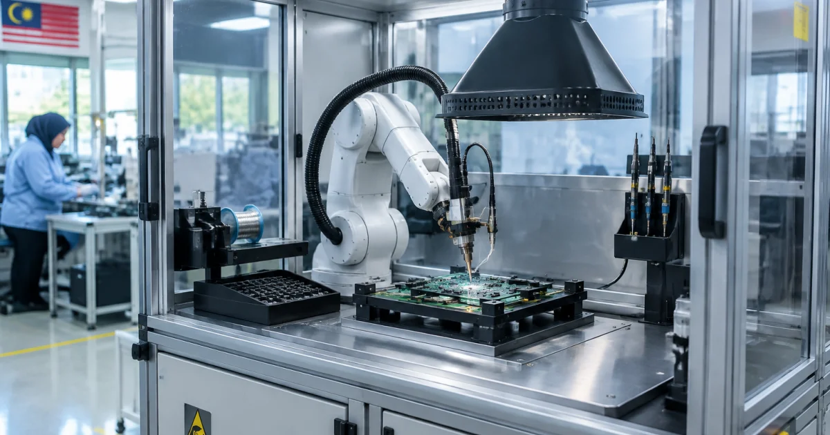
Integrating robotic soldering is less about buying equipment and more about engineering a repeatable process: stable fluxing, controlled thermal transfer, robust fixturing, and inspection that closes the loop. When these pieces are designed together, you get consistent joints, predictable cycle time, and less rework.
This tutorial is for electronics manufacturers planning a robotic soldering machine workcell (or upgrading an auto soldering setup). It outlines practical integration steps—from flux control through tip maintenance and quality verification—for through-hole pins, connector lugs, wire-to-pad joints, wire tinning, and selective touch-ups.
Scope note: temperature, dwell time, alloy, and flux type must be validated on your specific boards and components. Use the steps below to structure trials and commissioning so you converge quickly and avoid “parameter guessing.”
1) Define the soldering target: joint requirements, throughput, and constraints
Before programming paths or ordering tooling, align on what “good” means and what the line needs. This prevents a common failure: a cell that can solder, but not within your yield, takt time, or handling constraints.
Step 1.1: Document the joints and acceptance criteria
- Joint types: THT pins, lugs/terminals, wire tinning, wire-to-pad, shield tabs, ground pads, connector shells, etc.
- Materials: PCB finish, copper weight, component plating, wire gauge, and heat-sinking mass (connectors/shields).
- Access limits: tall nearby parts, keep-out zones, heat-sensitive bodies, plastics near pins.
- Quality definition: wetting coverage, fillet shape, void tolerance (if applicable), solder amount, bridging tolerance, cosmetic expectations.
Convert “looks good” into checks that can be trained and audited (wetting on both surfaces, no bridging, no solder balls in keep-out zones, acceptable fillet coverage).
Step 1.2: Translate production needs into engineering specs
- Cycle time target: include load/unload, indexing, fluxing, soldering, and any inspection.
- Changeover frequency: single model vs. multi-model; define quick-change fixturing and recipe management.
- Traceability: recipe IDs, operator login, per-board results (as required).
- Environment: ESD controls, fume extraction, and floor-space constraints.
Example: If you have 20 joints and a 30-second takt, handling time can leave under ~1 second per joint on average. That pushes you toward efficient approach/retract moves, minimal reorientation, and stable flux application (so you don’t “buy” yield with longer dwell time).
2) Build the process flow: fixturing, fluxing, soldering, cleaning, inspection
A robust integration starts with a repeatable sequence. Your robot program is only as stable as upstream positioning and downstream verification.
Step 2.1: Map a “single board” flow
- Load & locate: place the board/sub-assembly and constrain it.
- Pre-check (optional): presence/orientation via sensors or vision.
- Flux application: controlled amount, location, and time-to-solder.
- Soldering: approach, contact, heat transfer, solder feed, retract.
- Post-clean (optional): per flux type and customer requirements.
- Quality verification: visual/vision inspection, electrical test trigger, or operator confirmation.
- Unload: remove safely without contacting hot joints.
Do not leave “time-to-solder” undefined. Flux activation and wetting can shift dramatically if the delay between fluxing and heating varies with stoppages or handling.
Step 2.2: Decide what is automated vs. assisted
- Start by automating fluxing + soldering, while keeping manual load/unload if needed for speed-to-production.
- Add a vision station after the soldering process is stable to reduce subjective judgement and improve trending.
- Automate material movement later if the bottleneck shifts in higher volume or higher mix lines.
Prioritize the biggest repeatability drivers first: flux control, thermal control, and path consistency.
3) Flux control: consistency, placement, and timing
Flux is often the “invisible variable.” Too little can cause poor wetting; too much can drive residue, spatter, and contamination risk. In integration, flux must be metered, placed, and timed—not simply “applied.”
Step 3.1: Select a flux strategy that matches your joints
- Pen/needle dispensing: precise placement near pins/pads; easy to synchronize with robot motion.
- Spray fluxing: covers larger areas but increases overspray risk; needs containment and fume handling.
- Flux-cored solder: reduces separate fluxing steps, but still requires controlled heat and feed for consistent activation.
Example: For connector rows where bridging is a concern, needle dispense at the pin-to-pad interface is typically easier to control than a broad spray.
Step 3.2: Control volume, location, and dwell-to-solder time
- Volume: start at the minimum that yields reliable wetting; increase only if needed.
- Location: target the joint interface, not the surrounding area.
- Time: define an acceptable delay window between fluxing and soldering. If the line can pause, add a “re-flux after timeout” routine.
Practical control: add a timed “flux expiry” flag that blocks soldering after a delay, forcing re-flux or operator intervention. This avoids intermittent defects that are difficult to reproduce.
Step 3.3: Design for cleanliness and stability
- Use drip trays/shielding to protect fixtures, sensors, and enclosures from residue.
- Plan nozzle/needle cleaning intervals; clogging changes delivered volume.
- Include a startup purge routine to stabilize dispensing after idle time.
Flux residue can also reduce vision reliability, so coordinate flux selection and cleaning expectations early if you plan camera-based inspection.
4) Thermal setup and solder feed: turning “heat” into repeatable wetting
Robotic soldering consistency is mostly controlled heat transfer. The same set temperature can produce different results depending on tip condition, contact area, joint mass, and how solder wire is introduced. Integration aims to make those variables predictable.
Step 4.1: Establish a baseline soldering recipe per joint family
Group joints into “families” with similar geometry and thermal mass (e.g., small THT pins; large shield tabs; wire tinning). For each family, define:
- Approach angle and contact point
- Preheat/contact time before solder feed
- Solder feed rate and total feed length (or time-based feed)
- Dwell after feed to complete wetting/fillet formation
- Retract path to avoid stringing and contact with adjacent parts
Example: For lugs or shield tabs, adding a brief preheat dwell before feeding solder often reduces solder balling because solder isn’t introduced onto a cold surface.
Step 4.2: Control contact repeatability (not force)
- Use a consistent Z reference tied to a well-defined fixture datum.
- Prevent board flex near solder points to keep tip-to-joint geometry stable.
- Standardize tip selection so contact area is repeatable.
If you use compliant mounts or force/torque sensing, apply them to protect pads and components and to stabilize contact—not to “push harder.”
Step 4.3: Add preheating only when it reduces risk
Preheating can widen the process window for heavy joints, but it adds time and complexity. Consider it when:
- Large thermal mass joints require long dwell times that threaten nearby plastics/components.
- Wetting varies across boards due to copper plane or thermal spreading differences.
- You need to reduce tip contact time to improve throughput.
Document preheating as part of the recipe so results don’t depend on operator memory.
5) Workcell integration: fixture design, safety, fume extraction, and ESD
Many “programming problems” are mechanical: the board moved, datums shifted, or joints weren’t presented consistently. Strong fixture and workcell design turns your soldering machine into a controlled process.
Step 5.1: Design a fixture that locates, supports, and protects
- Locate: use repeatable datums (pins, edges, nests) so each load matches the taught position.
- Support: prevent flex near solder points; add standoffs under high-contact/thermal areas.
- Protect: keep-outs for tip travel; guard sensitive parts from accidental contact.
- Thermal considerations: avoid fixture materials that unintentionally sink heat near joints.
Example: For a PCB with a long connector row, mid-span support under the connector area can reduce Z variation and stabilize fillet formation across pins.
Step 5.2: Add poka-yoke to prevent wrong loading
- Asymmetric locating features to prevent reverse orientation
- Sensors to confirm clamps closed/part present
- A quick vision check before soldering starts
Simple error-proofing prevents expensive scrap and crash events during changeovers.
Step 5.3: Plan fumes and ESD during commissioning
- Fume extraction: capture close to the solder point without interfering with motion.
- ESD grounding: fixtures, operator touch points, and work surfaces should follow your ESD program.
- Safety: guarded zones, safe speeds for teaching, clear E-stop access.
A clean, controlled environment improves quality and maintainability, and makes vision inspection easier to deploy later.
6) Programming and calibration: paths, datums, and error-proof routines
With stable hardware, programming becomes a discipline: define coordinate systems, standardize motion primitives, and build recovery routines so small disturbances don’t become long downtime.
Step 6.1: Establish coordinate systems and “golden” references
- Cell reference: master datum for the workcell
- Fixture reference: coordinate system tied to the fixture (not the table)
- Product reference: offsets/recipes per model or revision
Use a repeatable calibration method and document it. Manual teaching without references tends to drift over maintenance and changeovers.
Step 6.2: Program in reusable “joint primitives”
- Approach: safe height and angle
- Contact: controlled descent with optional preheat dwell
- Feed: begin after stable contact
- Wet: post-feed dwell
- Retract: lift then move away to avoid stringing
Standard routines reduce debugging time and make tuning consistent across products.
Step 6.3: Add exception handling and recovery steps
- Tip temperature not ready: hold/alarm; don’t solder “cold.”
- Flux timeout: re-flux or block operation.
- Solder wire end/feed fault: safe stop, retract, prompt reload, resume from a controlled point.
- Board not clamped: block soldering to prevent crashes and scrap.
These routines often determine whether an auto soldering cell is production-ready or only demo-capable.
7) Tip maintenance and consumables: keeping heat transfer stable
Tip condition is a leading indicator of process stability. Oxidation, contamination, and wear change wetting and dwell time. Plan tip care as a standard routine—not tribal knowledge.
Step 7.1: Standardize tip selection and replacement criteria
- Tip geometry: match the joint; undersized tips increase dwell time, oversized tips increase collision risk.
- Replacement triggers: poor wetting, pitting, plating loss, or repeatable defects that disappear with a new tip.
- Spares: keep pre-tinned spare tips for quick change and consistent restart.
Example: If dwell time creeps up over days to maintain wetting, suspect tip degradation. Avoid “chasing” the issue by raising temperature indefinitely—restore the baseline with tip replacement and re-validation.
Step 7.2: Implement an in-process cleaning routine
- Startup: clean and tin to stabilize heat transfer.
- During production: periodic cleaning after a set number of joints or after heavy-mass joints.
- After idle: re-clean and re-tin before resuming.
Where supported, automate these steps to reduce variability between operators and shifts.
Step 7.3: Control consumables as part of the recipe
- Solder wire: alloy and diameter affect feed behavior and fillet size.
- Flux: lot/batch changes can shift performance; manage with quick checks.
- Nozzles/needles: wear/clogging changes flux volume and placement.
Maintain a simple change log so defects can be correlated to tip swaps, flux lots, and cleaning events.
8) Quality verification: visual criteria, vision inspection, and feedback loops
Verification is where integration becomes scalable. Manual inspection can work at low volume, but it is subjective and hard to trend. A structured plan—optionally with machine vision—helps maintain consistency across shifts and products.
Step 8.1: Start with a practical inspection plan (even before vision)
- Wetting on both surfaces (pad and lead/tab)
- Appropriate fillet shape/coverage for the joint type
- No bridging; no solder balls in critical zones
- No scorch/discoloration beyond your standard
Use photo examples from your own boards where possible. During trials, capture “pass/fail” images with short notes so production and QA align early.
Step 8.2: Where a robotic vision inspection system fits best
- Inline post-solder check: detect bridging, solder presence, and gross shape defects before unload.
- Pre-solder check: verify presence/orientation so you don’t solder the wrong part.
- Sampling station: inspect every N boards if cycle time is tight, with a containment plan for failures.
Vision performs best with controlled lighting, viewpoint, and cleanliness. Align defect taxonomy with your QC team to avoid production/QA disagreement on what is acceptable.
Step 8.3: Build a feedback loop for process drift
- If wetting declines across multiple joints: check tip condition and clean/re-tin.
- If bridging increases in one area: verify fixture support and Z repeatability, then confirm flux placement.
- If solder amount varies: inspect wire path/tension and recipe feed length.
Trend defects by joint family and shift. Even a simple log helps separate consumables issues from mechanical or programming causes.
Step-by-step commissioning checklist (put this on your shop floor)
- Confirm product definition: board revision, joint list, acceptance criteria, takt time target.
- Install/validate the fixture: repeatable loading, no flex at solder points, clear tip travel paths.
- Set up ESD and fume extraction: verify grounding continuity and capture near the joint area.
- Calibrate coordinate systems: cell, fixture, and product references; record the method.
- Validate flux delivery: purge, verify placement, confirm volume stability over repeated cycles.
- Establish baseline recipes: tune one joint family first until repeatable.
- Scale to all joints: copy primitives, then adjust only what must change (angles, dwell, feed).
- Add fault handling: flux timeout, temperature not ready, solder feed fault, clamp not detected.
- Implement tip maintenance: startup clean/tin, periodic cleaning schedule, replacement triggers.
- Run capability trials: long enough to see drift (oxidation, residue buildup, fixture heating).
- Lock down verification: operator checklist or camera criteria; define actions on failure.
- Train production: emphasize flux timing, tip care, and recovery steps to protect yield.
Common integration pitfalls (and how to avoid them)
These issues commonly appear when moving from manual soldering to an auto soldering machine in production.
Pitfall 1: Compensating for poor fixturing by changing solder parameters
If board position changes, you may see intermittent bridging or insufficient wetting. Fix mechanical repeatability first (support, clamps, datums), then tune dwell/feed.
Pitfall 2: Flux “looks fine” but time-to-solder varies
When the cell pauses, flux can dry or behave differently. Add a flux timeout and re-flux routine, and keep timing consistent.
Pitfall 3: Raising temperature to overcome tip degradation
This can mask the problem while increasing component risk. Use a maintenance plan: clean, re-tin, replace tips by defined triggers, and return to baseline recipes.
Pitfall 4: Adding inspection too late
If you plan for vision early (lighting, line-of-sight, mounting, cable routes), you avoid enclosure rework later. Even if vision is not deployed on day one, reserve the integration points.
Useful next steps for buyers: selecting the right soldering platform
When comparing soldering machine options, match platform capability to integration needs: axes and repeatability, solder feed method, fluxing method, recipe management, maintainability, and how easily you can add inspection and traceability later.
- Robotic Soldering Machine overview for integration planning and application fit.
- Chin Tech Robotic Soldering product category for different configurations and workloads.
- Chin Tech Ex399 Robotic Soldering Machine for compact automation cells and repeatable solder joints.
- Chin Tech Ex799 400 Robotic Soldering Machine for higher throughput needs and multi-joint programs.
- Chin Tech Ex 393 Robotic Soldering Machine as another option for production-focused soldering automation.
Conclusion: integrate the process, not just the robot
A successful robotic soldering integration is a chain: fixture repeatability enables stable tip contact; flux control enables consistent wetting; tip maintenance keeps heat transfer predictable; and verification prevents drift from becoming scrap. Commission in sequence—mechanics first, then flux, then thermal and feeding, then verification—to move from trial-and-error to a controllable, scalable process.
When you’re ready, involve an automation partner who can design the cell end-to-end (tooling, programming, sensors, and inspection) so your soldering automatic machine performs reliably on your actual products—not just in a demo.
Frequently Asked Questions
What should I prepare before integrating a robotic soldering system into my line?
Prepare a joint list (locations and types), clear acceptance criteria, expected cycle time per board, product variation/changeover needs, and fixture constraints (datums, keep-out zones, and access). Also confirm ESD and fume extraction requirements so the workcell design doesn’t need rework during commissioning.
How do I control flux consistency in automated soldering?
Treat fluxing as a controlled process: meter the volume, place it precisely at the joint interface, and keep the time between fluxing and soldering consistent. Add purge routines after idle time, plan nozzle/needle cleaning intervals, and implement a “flux timeout” rule that triggers re-fluxing if the line stops.
When does it make sense to add vision inspection to robotic soldering?
Add vision when you need objective, repeatable checks for solder presence, bridging, or gross fillet shape—especially across multiple shifts or high mix production. Plan lighting, camera angle, and cleanliness early. Many manufacturers start with an operator checklist, then upgrade to a vision station once the soldering recipes are stable.
Why do soldering results drift after a few days of stable production?
Common causes are tip oxidation/wear, flux residue buildup, nozzle clogging, and small fixture shifts or board flex. Instead of only increasing temperature or dwell time, use a defined tip cleaning/re-tinning schedule, replace tips based on triggers, and re-check fixture support and Z references.
Do you provide robot integration services for ASEAN manufacturers?
Yes. Chin Tech supports manufacturers in Malaysia and the ASEAN region with end-to-end automation system integration—from concept and system design to installation, programming, testing, commissioning, and long-term technical support for production optimisation.
Plan Your Robotic Soldering Integration With Chin Tech
If you’re evaluating automated soldering for consistent joints and higher throughput, Chin Tech can help you move from trial setups to a production-ready workcell. Our team designs and integrates complete solutions—robotic soldering systems, fixtures, sensors, and optional machine vision inspection—then commissions the process with practical flux control, tip maintenance routines, and verification criteria.
Share your board samples, joint list, and cycle time target, and we’ll recommend an integration approach that fits your space, quality requirements, and changeover needs.