
Vision inspection system Malaysia: how to choose, specify and integrate a reliable machine-vision inspection cell
Learn how to specify cameras, lenses, lighting, software and machine interfaces for a reliable vision inspection system in Malaysian manufacturing.
Vision inspection system Malaysia: how to choose, specify and integrate a reliable machine-vision inspection cell
A reliable vision inspection system starts with the inspection decision, not the camera. Define what must be detected, how quickly the part moves through production, and what the machine must do with the result. Those inputs determine the camera, lens, lighting, image-analysis software, triggering method and connection to the PLC, HMI, robot or reject mechanism.
This vision inspection system Malaysia selection guide is intended for manufacturers evaluating an inspection cell for electronics, semiconductor, precision-engineering or general production. Quality control is becoming more complex in semiconductor and electronics manufacturing, so a demonstration image is not enough: the proposed system must be tested with representative parts, acceptable variation and realistic production conditions.
Start with the inspection decision, not the camera
Before requesting a quotation, write a short inspection brief. State the feature or defect to identify, the smallest relevant variation, the way the part is presented, the required cycle time, and the action after a pass or fail decision. Also specify whether the process needs barcode or QR identification, production records, or communication with a PLC, HMI, robot or higher-level system.
This prevents a common purchasing mistake: comparing camera resolution or software features before confirming the production problem. An industrial vision system may improve inspection accuracy, consistency and scalability, but only when its design aligns with the specific production requirements. A supplier should therefore explain how the proposed setup handles part variation, movement, reflections, changes in presentation and the required machine response.
For semiconductor and electronics manufacturers, the useful question is not whether a supplier can demonstrate a successful image, but whether it can design and deploy a solution around the stated production requirements. That includes the component or assembly being inspected, the acceptable variation, the presentation method and the action required after classification. A system aligned with those conditions is more likely to remain practical when it moves from a controlled demonstration to the production line.
When comparing integrators, ask them to explain which parts of the proposed solution are application-specific: image acquisition, lighting, inspection logic, machine communication and physical handling. Request evidence from a representative trial rather than relying on a general capability statement. This approach helps distinguish a configurable vision platform from a complete inspection solution designed for the actual process.
Specify image acquisition around the part and process
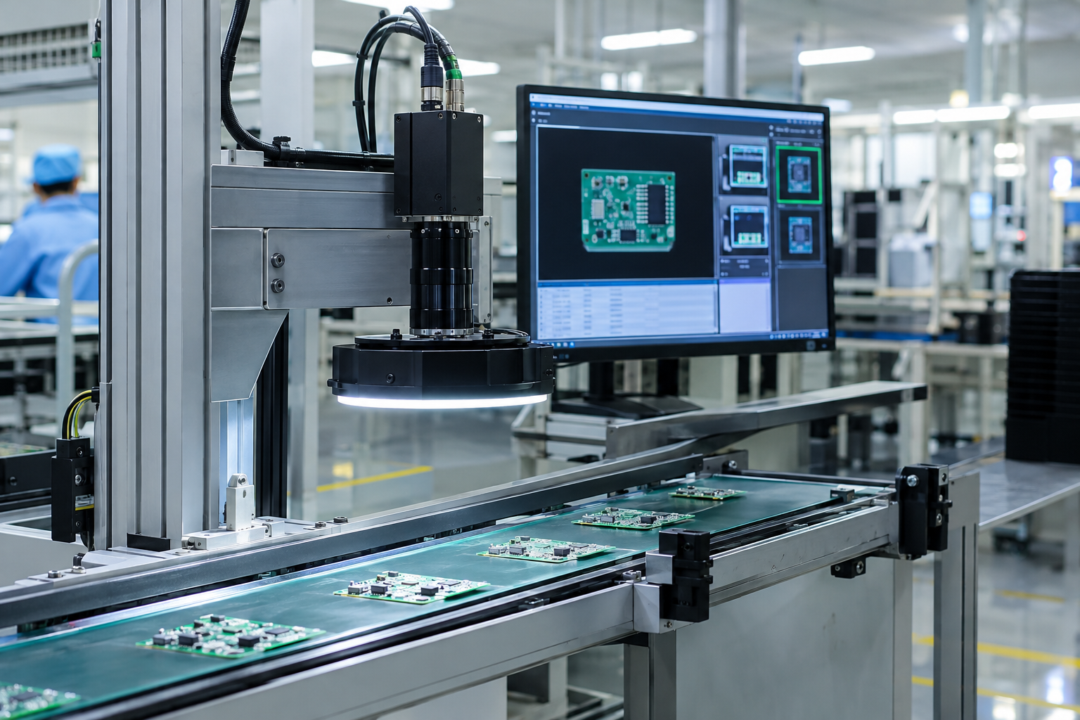
Camera selection is linked to working distance, lens characteristics, field of view, sensor sensitivity, wavelength, filters and object movement. Resolution should not be selected in isolation. The lens must show the inspection area clearly at the planned working distance, while the acquisition method must capture a sufficiently stable image as the part is stationary or moving.
Choose the camera and optics for the inspection task
An area-scan camera is generally considered when the complete inspection region can be captured in an image. A line-scan arrangement may be more suitable when the process presents a continuous web or a part that passes through the viewing area, but the supplier must confirm the scanning and motion conditions for the application. Two-dimensional inspection and three-dimensional inspection also answer different questions: surface appearance and printed information are not the same as height, profile or volume.
Ask the integrator to document the field of view, working distance, lens choice, expected object movement and triggering arrangement. If the part position changes between cycles, the fixture, conveyor or locating method becomes part of the vision specification. The Basler camera setup guide provides further context on controlling optics, lighting, triggering and calibration as one inspection chain.
Design the lighting before locking the vision software
Lighting is critical to robust machine-vision inspection because the software can only analyse the contrast captured by the camera. Effective design considers the inspection environment, sample presentation, camera sensitivity, illumination geometry, wavelength, filters, ambient light and motion. These factors should be reviewed together rather than added as an afterthought.
During trials, compare the lighting geometry with the visual feature being inspected. Backlighting can help reveal an outline or through-feature; diffuse lighting can reduce harsh reflections; bright-field lighting can illuminate a surface; and dark-field lighting can make certain edges or surface changes more visible. Strobes, filters and an enclosure may be useful where motion, ambient light or reflective materials make the image unstable. No single lighting type is suitable for every part or defect.
Require the trial to use actual production surfaces, finishes and presentation conditions. A clean image from a hand-positioned sample does not prove that the same contrast will remain when parts arrive on a conveyor, in a tray or through a feeder.
Integrate the vision result with the production machine
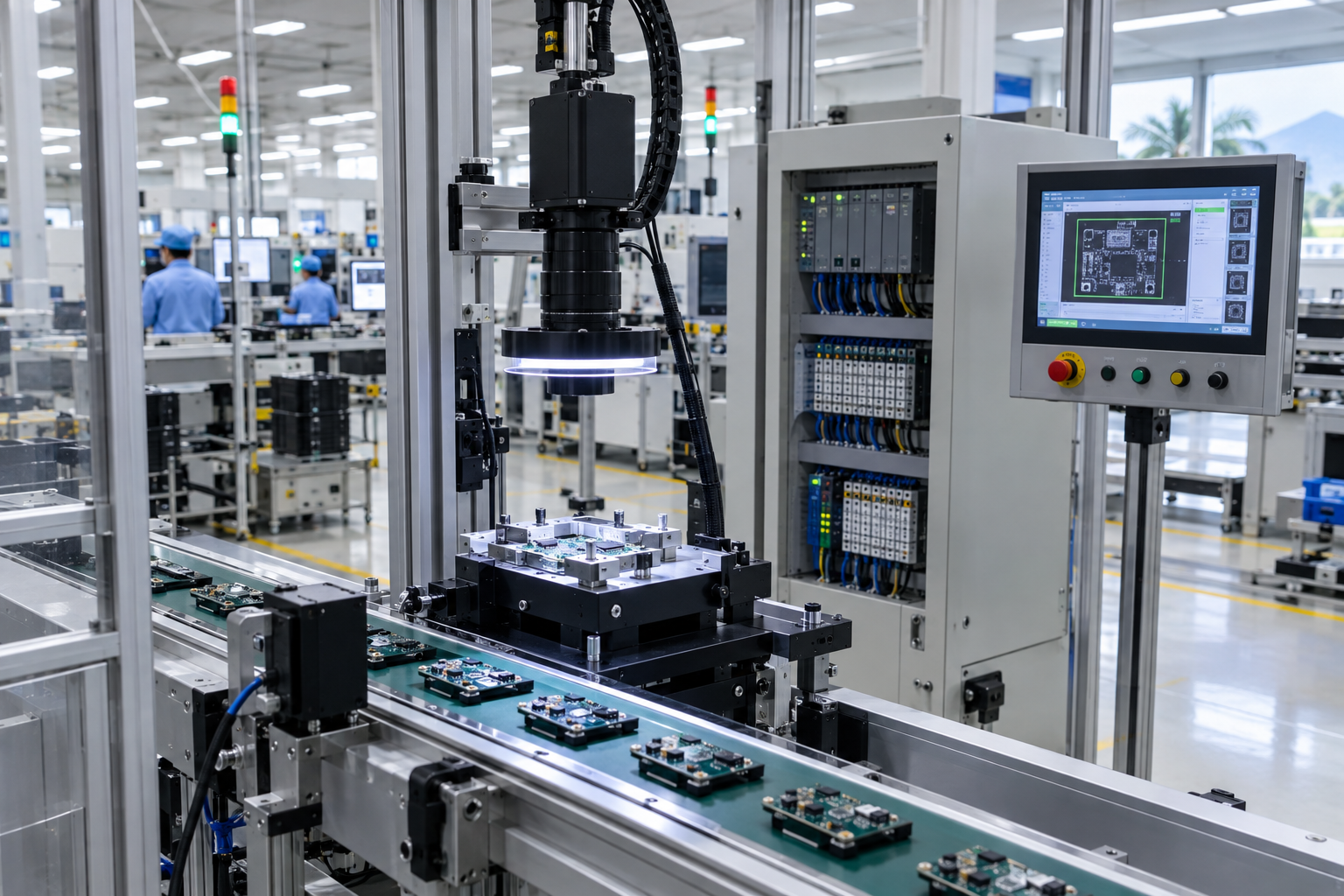
A vision inspection cell is more than a camera. Its core architecture normally includes a camera and imager, processor, image-analysis software, input/output hardware and communication links to devices such as HMIs, PLCs and robots. The system must identify the relevant feature, control image capture and illumination, analyse the result, and communicate the inspection decision to factory equipment.
Define the result path before installation. The specification should show how a part is triggered, how its image is associated with the correct part, how a pass or fail result is sent to the control system, and what happens if the image is missing, the code cannot be read, communication is interrupted or the reject action does not occur. Fixed timing values should not be assumed without checking the selected equipment and production layout.
For traceability, state the required barcode or QR data, record format, retention needs and system interface. For a robotic cell, clarify the handshaking between the vision system, robot and machine controller. For a reject station, include confirmation that the intended part was removed or diverted. These details turn an image result into a usable production control.
Use a trial-and-acceptance checklist before deployment
Request like-for-like proposals. Each supplier should respond to the same inspection objective, sample set, part presentation, cycle-time requirement, lighting conditions, interface design and data requirements. Local engineering support and integration capability are useful implementation considerations, but they do not replace application evidence or prove that a particular design suits your parts.
| Requirement to define | Specification to review | Verification before approval |
|---|---|---|
| Feature or defect to detect | Camera, lens, field of view and image-analysis method | Trial images using representative good and defective parts |
| Part presentation and movement | Fixture, conveyor position, trigger and exposure arrangement | Run samples in the intended production presentation |
| Surface and material variation | Lighting geometry, filters, wavelength and enclosure needs | Test finishes, reflections and normal part variation |
| Production response | I/O, PLC, HMI, robot or reject-station communication | Demonstrate pass, fail, missing-image and fault handling |
| Traceability | Barcode or QR reading, records and data interface | Verify the required data reaches the intended system |
| Deployment readiness | Documentation, calibration method and operator instructions | Repeat the agreed checks during factory acceptance and site acceptance |
Ask for an application trial or validation using representative good and defective parts before approving the design. Record image repeatability, false decisions, lighting stability, code-reading performance where relevant, cycle-time validation and the machine response to exceptions. The same acceptance logic should be carried through factory and site testing; Chin Tech’s URS, FAT and SAT guidance explains why measurable acceptance criteria and handover documentation matter in an automation project.
Malaysia’s MIDA-published SIRIM information sheet also identifies “Vision System” within automation-related equipment categories for Automation Capital Allowance purposes. This is equipment-category guidance, not confirmation that a particular project qualifies. Discuss the project scope and tax treatment with the relevant adviser before relying on it. Review the MIDA/SIRIM information sheet alongside the project documentation.
Frequently Asked Questions
What information should I provide for a vision inspection quotation?
Provide representative good and defective parts, the feature or defect to detect, the smallest relevant variation, required cycle time, part presentation, available space and the required PLC, robot, barcode or QR interface. These details allow the integrator to assess the camera, lens, lighting, trigger and communication requirements rather than quoting a generic package.
Can one camera and lighting setup inspect a high-mix production line?
It depends on the inspection tasks and how much the parts vary. A shared setup may be practical for similar presence or identification checks, but different surfaces, orientations or defect types may need different optics, lighting geometries or inspection stations. Validate the complete SKU range during an application trial before choosing a common setup.
When should a manufacturer request a custom vision-cell review?
Request a custom review when parts move during capture, surfaces are reflective, ambient light changes, presentation is inconsistent, several inspection tasks must be combined, or the machine response is not clearly defined. These conditions affect working distance, lens and lighting selection, triggering, image analysis and control integration.
What should acceptance testing cover?
Acceptance testing should cover repeatability on representative samples, false decisions, lighting stability, relevant barcode or QR reading, cycle-time validation, communication with the machine controller and recovery from defined exceptions. Agree the test method and evidence before factory acceptance, then repeat applicable checks at site.
Request an application review for your inspection cell
Prepare the inspection objective, good and defective samples, production speed, part presentation, installation space and intended PLC or robot interface. A structured application discussion can then focus on the real design decisions: image acquisition, lighting, triggering, machine communication and acceptance evidence. Contact Chin Tech to discuss your automation requirement.