
Specifying sensors looks easy on a P&ID—until commissioning. A device that “should detect the part” can fail in production due to glare, product variation, washdown, vibration, electrical noise, or late-stage mounting compromises. For controls engineers and maintenance teams, a clear specification reduces rework, nuisance stops, and guesswork during troubleshooting.
This practical guide for sick sensor malaysia sourcing and specification covers three common categories used across manufacturing and logistics: photoelectric sensors for detection, safety sensors for risk reduction, and distance sensors for measurement and control. The aim is to define requirements an integrator can implement and verify on site.
Start with a specification checklist (before choosing a sensor type)
Start by capturing application “non-negotiables.” Treat the sensor as part of a system: target, mechanics, electrical interface, and how you will prove performance.
1) Define the target and the failure mode
- Target properties: size, color, surface finish (shiny/matte/transparent), material, temperature, and expected batch variation.
- Motion profile: speed, vibration/acceleration, and whether the target can rotate or wobble (common on conveyors).
- Consequence of a miss: scrap, yield loss, gripper crash, or nuisance stop. Match sensing margin to risk.
2) Capture the environment and constraints
- Space and mounting: bracket locations, standoff distance, cleaning access, and cable routing.
- Ingress and chemicals: oil mist, flux fumes, coolant, washdown, dust, or powder.
- Ambient light and reflections: sunlight, high-bay LEDs, reflective guards, stainless steel, glossy film.
3) Specify electrical and controls interface
- Output/interface: PNP/NPN discrete, analog (0–10 V / 4–20 mA), or IO-Link/networked if diagnostics are needed.
- Response time: align with line speed and PLC scan; state any debounce/filtering limits.
- Connectors: M8/M12, straight/angled, and whether quick replacement is required.
4) Define acceptance tests
Document validation during FAT/SAT using real samples and realistic conditions:
- Minimum/maximum detection distance (or measurement range) with production parts
- False trigger tests (glare/background/empty conveyor)
- Repeatability over temperature and vibration (as applicable)
- For safety devices, functional tests and required stop performance checks
Testable criteria prevent “worked on the bench” surprises.
How to specify photoelectric sensors for reliable part detection
Photoelectric sensors are used for presence detection, counting, and triggering processes (labeling, inspection, pick-and-place). Selection depends mainly on target surface, background, and installation constraints.
Choose the sensing principle based on the target
- Through-beam: highest margin for long distances, small targets, and difficult surfaces; requires emitter/receiver mounting and alignment.
- Retro-reflective: single housing with a reflector; good for conveyors, but watch shiny/transparent products that can return light unpredictably.
- Diffuse (proximity): simplest mounting; most sensitive to target color/finish changes and background reflections.
- Background suppression (triangulation): helps when the background is close or reflective and you must avoid sensing the conveyor/fixture.
Practical specification fields to include
Instead of “detect a PCB,” specify measurable requirements:
- Detection distance window: reliable detection between X and Y mm given mechanical tolerances.
- Minimum target size: especially for small parts, leads, or partial occlusions.
- Background conditions: background distance, reflectivity, and whether a fixed background exists.
- Mounting orientation: preferred angle to reduce specular reflections.
- Teach method and lockout: teach-in vs potentiometer; whether settings must be lockable.
Common pitfalls (and how to prevent them)
- Shiny metals/soldered surfaces: prefer through-beam or background suppression; consider baffles to reduce stray reflections.
- Transparent packaging film: state if clear-object detection is required; retro-reflective with polarization or dedicated clear-object sensing may be needed.
- High-speed counting: define response time and ensure PLC input filtering does not mask pulses.
- Contamination/cleaning: specify cleaning access and, if available, diagnostics (e.g., contamination alarms).
Reliable photoelectric detection is usually a mechanical + optical design decision, not just a datasheet choice.
How to specify safety sensors: light curtains, scanners, and interlocks
Safety sensing is about the full safety function: the hazard, required performance, machine stopping behavior, integration method, and validation plan.
Translate the hazard into a sensing requirement
- What needs protection? point of operation, pinch points, robot cell entry, palletizer infeed, conveyor transfers.
- Who is exposed? operators, maintenance staff, forklift traffic, occasional access during changeover.
- How is access made? walk-in, reach-over, reach-through, or bypass routes during maintenance.
This drives whether you need a safety light curtain, safety laser scanner, safety door switch/interlock, enabling device, or a layered combination.
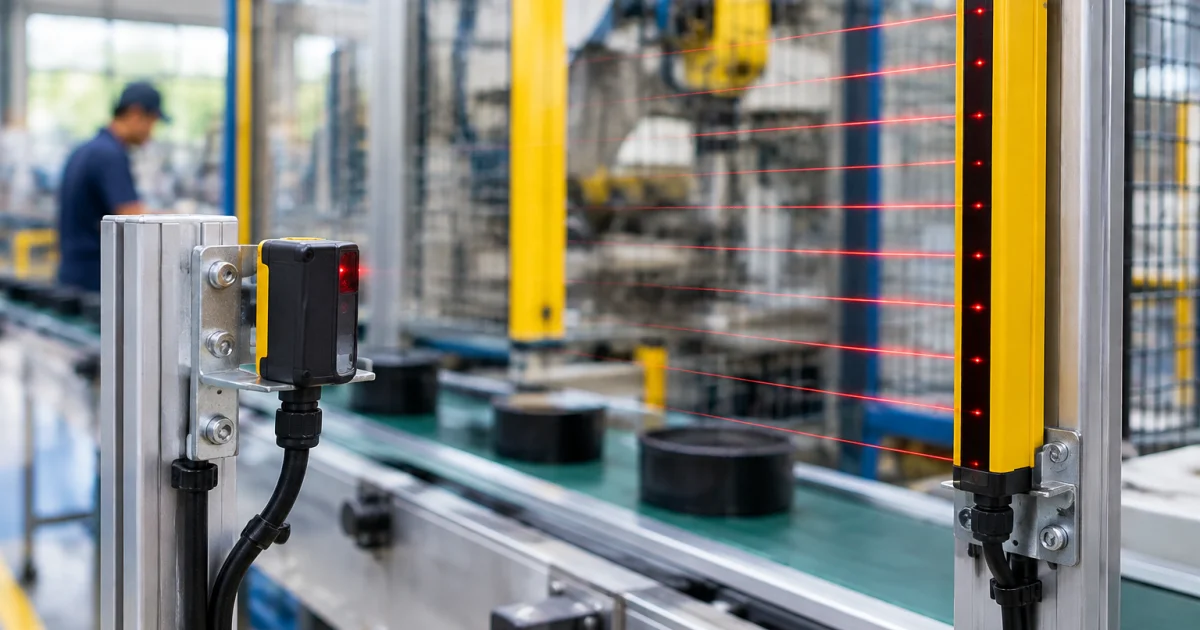
Light curtain specification essentials
- Protective height/coverage: mounting height and any gaps created by conveyors, supports, or product flow.
- Resolution: specify detection capability (finger/hand/body) and minimum object size.
- Muting/blanking: if product/pallets must pass, define muting logic, muting sensors, and anti-bypass measures.
- Restart/reset: manual reset location, line-of-sight to the hazard zone, and prevention of unexpected start.
Safety laser scanners and distance monitoring
For flexible layouts (shared aisles, space constraints, changing access points), safety scanners provide configurable warning and protective fields. Specify:
- Field shapes and approach directions
- Speed-dependent field switching (if applicable)
- Environmental concerns (dust/mist) and cleaning access
- Integration with the safety controller and stop categories
In intralogistics projects (including an amr machine application), scanner fields often pair with physical guarding or interlocked gates at fixed hazards.
Verification: make validation part of the plan
Strengthen your spec by defining how the safety function will be tested during commissioning:
- Trip tests from different angles/heights
- Stop-time confirmation after installation changes
- Fault simulation (e.g., cable disconnect) to confirm safe state
How to specify distance sensors for measurement, positioning, and quality checks
Distance sensing is used when “present/not present” isn’t enough—gap/height control, placement verification, fill level, warp detection, or feedback to actuators. Success depends on matching technology to surface and accuracy needs.
Decide what output you need: switching vs measurement
- Switching distance sensor: discrete output at a threshold for simple position/stroke checks.
- Measuring sensor: continuous distance data (analog or IO-Link) for closed-loop control, trending, and tighter tolerances.
Specification fields that prevent underperformance
- Range and standoff: include tolerance stack-up so operation stays within the sensor’s optimal region.
- Accuracy vs repeatability: define what matters to the process (repeatability is often the key).
- Surface/angle constraints: shiny/dark/textured targets; state whether multiple product variants must be handled.
- Update rate: critical for moving targets and robot guidance.
- PLC data usage: specify desired diagnostics (signal quality, contamination warnings, temperature compensation).
Where distance sensors fit with machine vision
Distance sensing and vision often complement each other: a distance sensor can stabilize a camera’s working distance or trigger inspection; vision can verify orientation, codes, or cosmetic defects. If your project includes a robotic vision inspection system or other vision inspection machines, specify:
- How the sensor triggers inspection (edge/position window/encoder gating)
- Reject handling (timing, diverter actuation, buffer spacing)
- How to reduce false rejects from lighting changes or part height variation
This is especially relevant in electronics lines where processes like auto soldering or a soldering machine station can add reflections or residue that affect optical sensing and inspection consistency.
Integration details that matter: mounting, wiring, diagnostics, and maintenance
Even the right sensor can underperform if mounting and integration are weak. Build these requirements into the specification to reduce downtime over the machine’s life.
Mounting and mechanical design
- Rigid brackets: prevent drift; specify stiffness/anti-vibration features for high-cycle machines.
- Adjustability: include fine adjustment where alignment is critical (through-beam, retro-reflective, light curtains).
- Protection without blocking: guards should not create blind spots or trap contamination in the optical path.
- Cable strain relief: prevent intermittent faults from movement and maintenance pulls.
Wiring and panel considerations
- Standardize connectors: consistent M8/M12 choices simplify spares and shorten recovery time.
- Noise/grounding: route away from VFDs and high-current cables; specify shielding and termination where needed.
- Input monitoring: for critical detection, consider plausibility checks/monitoring rather than relying on a single bit.
Diagnostics and maintainability
- Service-visible indicators: LEDs visible from normal access points.
- Actionable alarms: where supported, distinguish “blocked,” “misaligned,” and “signal weak.”
- Commissioning record: taught settings, distances, and pass/fail criteria for repeatable troubleshooting.
Useful next reads and product resources
If your project includes robots, inspection, or intralogistics, sensor selection is a foundational layer. These resources may help during planning:
- Sick sensors and accessories catalog overview
- Sick 3D LiDAR Sensors MRS1000
- 3D LiDAR Sensors MRS6000
- 6 Axis Force Torque Sensor
Considering the full cell—mechanics, controls, safety, and inspection—helps you build a stable, testable specification from day one.
Conclusion: specify requirements you can test, not just a sensor model
The most reliable sensor choice comes from a clear, testable specification: target characteristics, environment, mounting constraints, electrical interface, and acceptance tests. Photoelectric sensors succeed when you match the sensing principle to surface/background; safety sensors require hazard-based requirements and validation; distance sensors perform when you define range, repeatability, and how data will be used in controls and inspection.
Document these requirements up front to reduce nuisance trips, speed commissioning, and give maintenance teams a system they can troubleshoot quickly—on conveyors, in robot cells, or at inspection stations.
Frequently Asked Questions
How do I choose between through-beam, retro-reflective, and diffuse photoelectric sensors?
Use through-beam when you need the highest detection margin, long sensing distance, or reliable detection of small/difficult targets. Use retro-reflective when you want a single-sided sensor with a reflector on the opposite side, but account for shiny or transparent products that can cause false returns. Use diffuse when mounting space is tight and the target surface is consistent; add background suppression when the background is close or reflective.
What details should be included in a sensor specification to avoid site rework?
Include a detection or measurement window (min/max distance), minimum target size, target surface characteristics (color, gloss, transparency), environmental factors (dust, washdown, ambient light), mounting constraints (space, access, bracket rigidity), electrical interface (PNP/NPN, analog, IO-Link), response time, connector type, and clear FAT/SAT acceptance tests using real product samples.
When should I use a safety light curtain versus a safety laser scanner?
Safety light curtains are typically best for guarding fixed access points with a clear boundary (e.g., machine openings or conveyor transfers) and predictable approach direction. Safety laser scanners are useful when access is more flexible, the area shape changes, or you need configurable protective and warning fields (e.g., shared aisles, variable stations, or mobile robotics zones). In many cells, a combination of fixed guarding and scanners provides the most practical coverage.
Are distance sensors a good alternative to machine vision for inspection?
Distance sensors are excellent for measuring height, gap, presence with thresholds, or providing stable triggers for an inspection station. Machine vision is better when you must verify orientation, read codes, check cosmetic defects, or inspect complex features. Many production lines combine both: a distance sensor controls the inspection timing/working distance, while vision performs feature-based verification.
What are common causes of false triggers in photoelectric sensing, and how can I prevent them?
Common causes include specular reflections from shiny metal, clear film or glossy packaging, strong ambient lighting, and background detection when the target is small or inconsistent. Prevention methods include choosing through-beam or background-suppression types, adjusting mounting angles, adding baffles or shielding, ensuring stable brackets, and specifying diagnostics/alarms for contamination or misalignment so issues are caught early.
Plan your sensor specification with Chin Tech
If you’re designing or upgrading a line and need help selecting photoelectric, safety, or distance sensing that will survive real production conditions, Chin Tech can support you from requirements to commissioning. As an end-to-end automation system integrator, we combine industrial sensors with machine vision & inspection systems, robotic cells (including cobots and robotic soldering systems), and intralogistics solutions such as AMRs—so the sensor choice fits the full system, not just a datasheet.
Share your application details (target, speed, environment, mounting constraints, and acceptance criteria), and our engineering team will help translate them into a practical, testable sensor and integration plan.